Duke4.net Forums: EDuke32 2.0 and Polymer! - Duke4.net Forums

Jump to content

  • 213 Pages +
  • « First
  • 149
  • 150
  • 151
  • 152
  • 153
  • Last »
  • You cannot start a new topic
  • You cannot reply to this topic

EDuke32 2.0 and Polymer!  "talk about the wonders of EDuke32 and the new renderer"

User is offline   Helixhorned 

  • EDuke32 Developer

#4490

I see it now, it's really too bright in the game. I was testing in the editor and assumed that it would look the same in-game. More mysteries when I believed to have uncovered them all. Don't base your maps on this new mode yet.

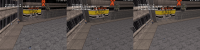
EDIT: false alarm. I set r_shadescale to 0 for testing purposes. :) Pictures upcoming.
0

User is offline   Fox 

  • Fraka kaka kaka kaka-kow!

#4491

Mode 1, ignoring HUD sprites, was very close to 8-bit.
0

User is offline   Helixhorned 

  • EDuke32 Developer

#4492

View PostFox, on 26 March 2014 - 11:03 AM, said:

Mode 1, ignoring HUD sprites, was very close to 8-bit.

No, it was way off. Classic has a linear fog/visibility model, whereas mode 1 is GL_EXP2.

EDIT: Actually, in some aspects it may have been closer to classic than modes >= 2. Just a bit patience, I'll explain everything in a moment.
0

User is offline   Helixhorned 

  • EDuke32 Developer

#4493

OK, let's first review how shading and visibilty work in classic. When an object is drawn, for each pixel [*] of that object, a shade index is determined according to a single formula:

shidx = clamp(shade + C*visdist, 0, Numshades-1)

Here, shade is the object's shade while visdist is the product of some visibilty and the distance from the eye to that particular pixel. In other words, shade is constant throughout the object, but visdist in general changes for each pixel (in shader terminology, one is uniform and the other is varying).

Spoiler

Clearly, the shade index is always greater or equal than the object's shade, and increases linearly with both distance or visibility (keeping the respectively other constant) until the maximum index, Numshades-1, is reached.

Given that formula, we can turn it "inside out" and instead ask for the starting and ending distances of a linear fog. At the starting distance, there's no attenuation, whereas at the ending one, it's fully black. E.g for the ending distance, plugging Numshades-1 into shidx and solving for visdist gives:

Numshades-1 = shade + C*visdist
-->
visdist = (Numshades-1-shade) / C
or
distend = (Numshades-1-shade) / (C*vis)


So far, so good. Let's see the starting distance. Plugging 0 in shidx and doing the same procedure, we get

0 = shade + C*visdist
-->
visdist = -shade / C
or
diststart = -shade / (C*vis)


This is exactly the pair that I introduced with r_usenewshading 2. But there's a problem with it: in determining the starting distance this way, we assume that no brightness attenuation has previously been applied to the object! To see why, consider the attenuation at distance zero,
(0 - diststart) / (distend - diststart) = shade / (Numshades-1).

Since in Polymost, objects are drawn with shading already applied (either using glColor(), or with r_usetileshading, by using a texture obtained by doing the palookup on it), we're doing the intended shading twice. This is the only thing that was changed: with r_usenewshading 3, the starting distance is always zero, reflecting the fact that the object has already been shade-attenuated. The ending distance remains the same, so the overall change is a homogenous increase in brightness for any set of objects with equal visibility.


Now, how does the new mode fare in practice? It is more faithful to classic as far as ratios of shade are concerned. For example, looking at the cinema entrance in E1L1,

Attached Image: shade_ratios.png
the sector below the announcement tableau has infinite visibilty (240) and shade 11. The surrounding sidewalk has shade 4 and finite visibilty 0. [**]

Spoiler

Since the inner sector's floor always has the same brightness independent of distance, moving closer to it will make the sidewalk brighter in comparison, while moving away from it will make it darker. At a certain distance, both appear of the same brightness. This distance where both effects offset each other is correct with r_usenewshading 3, but wrong with the old mode.

After having made the screenshots (gamma-corrected to 1.5 with ImageMagick), I do notice that the sidewalk appears brighter than in classic with the new mode now. However, for me, the difference doesn't look so striking in-game for some reason.


----------
This was part one of Helix' explanation of EDuke32 shading. Stay tuned for part two, wherein the mysteries of r_usetileshades are unveiled and an attempt is made to convince everyone that r_usetileshades 2 is in a certain respect more faithful in reproducing classic (but less so in another one).

Edit: corrected horizontal <-> vertical in the first spoiler.
2

User is offline   Fox 

  • Fraka kaka kaka kaka-kow!

#4494

I think the brightness problem is more with the shade table than visibility.

Here are two images. On the left is a image I created from Duke 3D shade table. I took the difference from the average of the 32 gray colors. On the right is r_usetileshades 3, which simply incresements the RGB values of each shade by 1/32. Needless to say the result is quite not accurate.

Posted Image

Here is the image I created applied on Duke 3D gray colors. While the individual pixels are not the same, the average color of each line (table) is exactly the same.

Posted Image

And here is r_usetileshades 3.

Posted Image

Edit: Chart

Red - Duke 3D shade table
Blue - Eduke32 OpenGL
Posted Image

If it's to use a straight line, one that ends at 30 instead of 32 would be better.

This post has been edited by Fox: 26 March 2014 - 06:12 PM

0

User is offline   Stabs 

#4495

so whats the deal with polymer it just renders way too much which becomes apparent in wireframe mode, cant that be made more intelligent system its the whole reason the FPS loves to bomb.
0

User is offline   Plagman 

  • Former VP of Media Operations

#4496

It uses occlusion to determine what to draw, so in wireframe since you see through everything it renders more stuff :-)
0

User is offline   Mark 

#4497

I just tried out the wireframe mode. Looks cool. What I immediately noticed was that when the map is converted to "model" form in the game that many extra walls are created that were not put in through mapster. I'm not referring to the diagonal line added to a square or rectangle, like in a modelling program, but extra walls extending out from a corner to other sectors for example. I wonder how many more polys are added in the whole map. A lot !!

Attached thumbnail(s)

  • Attached Image: duke0001.jpg
  • Attached Image: duke0000.jpg


This post has been edited by Mark.: 27 March 2014 - 12:49 PM

0

User is offline   Jblade 

#4498

They're not walls, they're polygons. The renderer has to do that in order to work.
0

User is offline   Kyanos 

#4499

View PostMark., on 27 March 2014 - 12:41 PM, said:

I just tried out the wireframe mode. Looks cool. What I immediately noticed was that when the map is converted to "model" form in the game that many extra walls are created that were not put in through mapster. I'm not referring to the diagonal line added to a square or rectangle, like in a modelling program, but extra walls extending out from a corner to other sectors for example. I wonder how many more polys are added in the whole map. A lot !!

I bet many maps could be optimized to take the guess work out of polymer`s triangulation. I bet every poly needs to be 3 sided, with 3 verts. Extra points make extra tri`s.
0

User is offline   Mark 

#4500

I can't imagine the trouble of having to map in triangles to closely match the renderer.. :) I know the detail of my previous pics is hard to see, but how the renderer determines those extra polys is beyond me. If I was building a model I wouldn't have made it that way. But I'm sure there is a very technical reason that I couldn't begin to understand.

This post has been edited by Mark.: 27 March 2014 - 03:31 PM

0

User is offline   Micky C 

  • Honored Donor

#4501

As Plagman would say, it's easier to make it and have it work as opposed to have it work efficiently.
0

User is offline   Kyanos 

#4502

View PostMark., on 27 March 2014 - 03:28 PM, said:

I can't imagine the trouble of having to map in triangles to closely match the renderer.. :) I know the detail of my previous pics is hard to see, but how the renderer determines those extra polys is beyond me. If I was building a model I wouldn't have made it that way. But I'm sure there is a very technical reason that I couldn't begin to understand.

Attached Image: blender_triangulate.PNG


I had to compare the two. Blender has an automatic face triangulation feature too, I used it in the md3 export script, both make 6 faces for an octagon, but in different ways.

About my earlier comment, if you made all your sectors out of triangles I think Polymer would not change anything than to triangulate wall faces. It's odd shaped sectors with many points that end up as many faced polygons. By no means am I referring to anything I saw in your pics, it just a generalization by me.
0

User is offline   Mark 

#4503

I suppose the renderer is doing something like the "simplify mesh" command in my modelling program. This is an end view of a cylinder before and after the command. It shaves a few faces off the model while retaining its original look.

Attached thumbnail(s)

  • Attached Image: beforeafter.jpg

0

User is offline   Stabs 

#4504

yes i highly recommend you square of circular edges on sectors lest it make a fuckton of very long triangles. unused points that serve no purpose make further triangles and unnecessary rendering

btw plagman i thought wireframe showed you exactly whats being rendered in normal mode, so its only rendering the whole map cause of wireframe, because you can stand in one spot and it dosnt display the whole level, rotate to left or right a little bit and the whole level can just show up

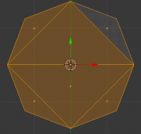
This post has been edited by Stabs: 27 March 2014 - 07:01 PM

0

User is offline   Gambini 

#4505

View PostMark., on 27 March 2014 - 05:05 PM, said:

I suppose the renderer is doing something like the "simplify mesh" command in my modelling program. This is an end view of a cylinder before and after the command. It shaves a few faces off the model while retaining its original look.


It doesn´t retain its original look. What you have there is a ONE POLYGON less cyllinder that will surely look horrible ingame. When polygons become so long and thin like in your 2nd image, smoothing (and possibly lighting, depending on the engine) will show ugly polygons interpolation. I, by practice, cut the polygons manually on my models before triangulating.
0

User is offline   Stabs 

#4506

View PostGambini, on 27 March 2014 - 09:06 PM, said:

It doesn´t retain its original look. What you have there is a ONE POLYGON less cyllinder that will surely look horrible ingame. When polygons become so long and thin like in your 2nd image, smoothing (and possibly lighting, depending on the engine) will show ugly polygons interpolation. I, by practice, cut the polygons manually on my models before triangulating.


pretty much, vectors are the future they have none of those constraints, we only just now have large scale vector engines like minecraft

come on carmack make that super vector ray trace engine already
0

User is offline   Mark 

#4507

View PostGambini, on 27 March 2014 - 09:06 PM, said:

It doesn´t retain its original look. What you have there is a ONE POLYGON less cyllinder that will surely look horrible ingame. When polygons become so long and thin like in your 2nd image, smoothing (and possibly lighting, depending on the engine) will show ugly polygons interpolation. I, by practice, cut the polygons manually on my models before triangulating.

I don't have much of a choice with the program I use. It creates ONLY in triangles. I'll have to take a closer look at a bunch of my models. I haven't noticed the interpolation you mentioned. The first time I used the "simplify mesh" command and saw the wireframe results I also thought it would screw up the looks. Maybe the way the program wraps the skin around the object takes it into account. BTW, that command saved 4 faces not 1. :) 
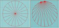
Here is an example of a model I made for the HRP using the poly reducing method which reduced by 80 faces. It looked fine to me from all angles.But enough of this. I'm getting off topic.

Attached thumbnail(s)

  • Attached Image: test.jpg


This post has been edited by Mark.: 28 March 2014 - 04:58 PM

0

User is offline   Fox 

  • Fraka kaka kaka kaka-kow!

#4508

I got a small problem with tilefromtexture... yoff -1 is not working, instead the value is set to zero.
0

User is offline   Helixhorned 

  • EDuke32 Developer

#4509

View PostMark., on 27 March 2014 - 12:41 PM, said:

I just tried out the wireframe mode. Looks cool. What I immediately noticed was that when the map is converted to "model" form in the game that many extra walls are created that were not put in through mapster. I'm not referring to the diagonal line added to a square or rectangle, like in a modelling program, but extra walls extending out from a corner to other sectors for example. I wonder how many more polys are added in the whole map. A lot !!

Polymer uses the gluTess* functions to tesselate ceilings/floors simply because it needs triangles futher down in the pipeline. As for the count... a polygon with N >= 3 vertices tesselates to N-2 triangles, so you could say that the number of triangles is roughly proportional in the number of walls. Nothing to worry about.

View PostDrek, on 27 March 2014 - 03:16 PM, said:

I bet many maps could be optimized to take the guess work out of polymer`s triangulation. I bet every poly needs to be 3 sided, with 3 verts. Extra points make extra tri`s.

I don't think that the tesselation is a bottleneck.
0

User is offline   Helixhorned 

  • EDuke32 Developer

#4510

View PostFox, on 29 March 2014 - 11:59 AM, said:

I got a small problem with tilefromtexture... yoff -1 is not working, instead the value is set to zero.

Should be fixed with r4402, tough I didn't test it.
1

User is offline   Plagman 

  • Former VP of Media Operations

#4511

The only problem with the current tessellation approach is that with forward rendering, triangles are rendered once per light that affects them. Sectors can create triangles with extremely large areas, which will end up rendered fully for every small light that touches them. That is why breaking down big sectors in smaller sectors is sometimes a performance win, as fill rate can become an issue. One optimization that would help with the current scheme would be to project the light volume onto the screen before doing a light pass, and set a scissor rectangle to the boundaries of that area before rendering the affected geometry. The real fix would be to move to a deferred approach.
1

User is offline   Fox 

  • Fraka kaka kaka kaka-kow!

#4512

View PostHelixhorned, on 29 March 2014 - 02:12 PM, said:

Should be fixed with r4402, tough I didn't test it.

It's working now, thanks.
0

User is offline   Hendricks266 

  • Weaponized Autism

  #4513

View PostHelixhorned, on 29 March 2014 - 02:12 PM, said:

Should be fixed with r4402, tough I didn't test it.

Oh, fuck. Somehow I thought that ~0 would be INT32_MAX when it's really -1. That trick only works with unsigned numbers (UINT32_MAX).
0

User is offline   Helixhorned 

  • EDuke32 Developer

#4514

View PostPlagman, on 29 March 2014 - 02:44 PM, said:

Sectors can create triangles with extremely large areas, which will end up rendered fully for every small light that touches them. That is why breaking down big sectors in smaller sectors is sometimes a performance win, as fill rate can become an issue.

I stand corrected then. Thanks for the clear explanation!
0

User is offline   Micky C 

  • Honored Donor

#4515

What about Parkade and CBP 8 which are also kinda slow even with lights disabled?
0

User is offline   Stabs 

#4516

something wrong with VIS again in 4402 with this new shading, still very bright and now does this in DNE07

in game 4402

Attached Image: eduke32 2014-03-30 11-56-17-35.png

mapster 4402

Attached Image: mapster32 2014-03-30 11-55-39-80.png

I noticed that firing your weapon now removes the fog, i could of sworn that got removed earlier

so shading mode 3, it needs pals on walls now for them to be effected by fog?

This post has been edited by Stabs: 29 March 2014 - 05:56 PM

0

User is offline   Fox 

  • Fraka kaka kaka kaka-kow!

#4517

Sector filler should totally be used for rendering fog separately from pal, instead of blend which is defective in OpenGL and unavailable for masked walls.

Just saying.

This post has been edited by Fox: 29 March 2014 - 06:45 PM

0

User is offline   Helixhorned 

  • EDuke32 Developer

#4518

View PostStabs, on 29 March 2014 - 05:01 PM, said:

something wrong with VIS again in 4402 with this new shading, still very bright

I'll return to the brightness issue later.

Quote

and now does this in DNE07

in game 4402

Attachment eduke32 2014-03-30 11-56-17-35.png

mapster 4402

Attachment mapster32 2014-03-30 11-55-39-80.png

What exactly differs from previous versions there? The in-game one looks pretty bad, but I just tested out that map, and it looked OK. (Note: a few EDuke32 commits were made in between.)

It seems that you're using r_usenewshading 3 in-game, but 2 in the editor. Always make sure that you sync these variables, none of the apps will do that for you.

As for the effects you're seeing: as mentioned earlier, r_usenewshading 3 will never produce negative fog starting distances. This is the reason why the screen is tinted overall by the fog with mode 2, but starts untinted with mode 3.

Quote

I noticed that firing your weapon now removes the fog, i could of sworn that got removed earlier

No, that was never removed. That looks like another consequence of what I said above. With mode 2, if you have non-infinite visibility, there's some attenuation at distance 0 already, which is especially noticeable with colored fog.

Quote

so shading mode 3, it needs pals on walls now for them to be effected by fog?

No, fog should be taken over from a wall's sector. I couldn't reproduce a case where I would need to set a wall's pal to a fogpal separately, either. What makes you think so?
0

User is offline   Helixhorned 

  • EDuke32 Developer

#4519

View PostFox, on 29 March 2014 - 06:44 PM, said:

Sector filler should totally be used for rendering fog separately from pal, instead of blend which is defective in OpenGL and unavailable for masked walls.

Are you suggesting to use sector[].filler / blend (it's the same member!) for a different purpose in the GL modes than when in classic? I think that's a bad idea. It would necessiate writing code conditional on the current rendering mode when dealing with that member then, both internally as well as from CON. (Ideally, mods should be agnostic to the rendering mode.)

There is wall[].blend in Lunatic. It will simply be not available in the non-Lua builds because that would require extending the on-disk binary map format. That has nothing to do with sector[].blend, though.
0

Share this topic:


  • 213 Pages +
  • « First
  • 149
  • 150
  • 151
  • 152
  • 153
  • Last »
  • You cannot start a new topic
  • You cannot reply to this topic


All copyrights and trademarks not owned by Voidpoint, LLC are the sole property of their respective owners. Play Ion Fury! ;) © Voidpoint, LLC

Enter your sign in name and password


Sign in options